SWAN 100MX MODIFICATIONS
![]() 27-01-2011 Schematics.
27-01-2011 Schematics.
SELF OSCILLATING (10m)
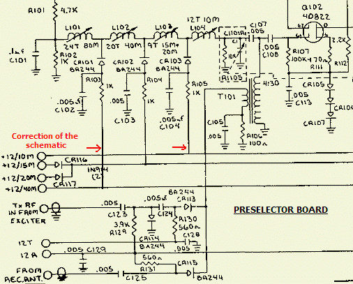
If the PRESELECTOR is tuned for 10 m resonance, the set oscillates already when PTT is pressed in USB or LSB mode. I was days and nights searching for failures. Damping circuits, reducing gain or more feedback in the transistor amplifier was not a real improvement. However, the conclusion was that for almost 100% the malefactor was in the Preselector.
Some US hams reported me: " (1) I had the same problem with mine & never did get to the bottom of the problem. My 100MX have been setting on the shelf now for over a year. " (2) "That is exactly what mine does! I had come to the conclusion that there were to many interdependent circuits in this radio. Another member of this group had the same problem at the same time. I don't know if he ever fixed it or not."
PAØFVE pointed me to an irregularity in the schematic that might cause an unwanted positive feedback. However it was a drawing error, and (fig») the proper connections are now marked with an arrow.
MODIFICATION
|
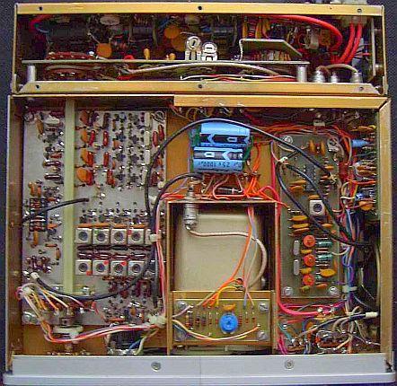
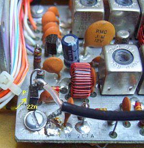
Components at the track side. |
Richt: a ferrite bead over the inner conductor. |
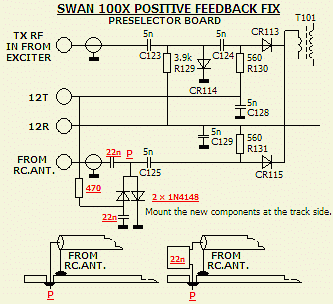
Because the phenomenon only occurred at 10 m, I suspect the (zero) capacitance of CR115 (BA244) as culprit. When the relevant coax cable was disconnected, the 10 m band was pretty stable with nice "trees" pictures on a scoop. Indeed, both transmitter and receiver sections uses the Preselector, e.g. the signals passes through the Antenna Relay to input and output. In transmit mode a leakage RF current passes as positive feedback through C125 and CR115 to T101.
The schematic shows how the fix is done. During transmit the input of capacitor C125 is electronically short-circuit to ground with two diodes. Desolder the inner conductor of the cable and mount a 22-100 nF capacitor into the hole. That is the point P in the diagram. Then solder the coax at the other side of the capacitor and mount the rest of the components on the track side, see the first photo. After this operation the stability was not always good and it was solved by sliding a ferrite bead over the inner conductor at the "beginning" of the coaxial cable.
OVERDRIVE
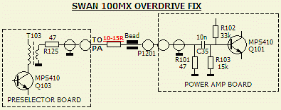
At the next QSO's I got the report that there was still something wrong with the modulation. It sounds like RF feedback. The cause was first sought in the microphone, then the slightly odd microphone amplifier and then to a possibly non-linear behaviour of the transistor amplifier (AMP POWER BOARD). Ultimately it was overdrive of the PA. Apparently, the engineers of Atlas were evenly confronted with the problem, given the presence of R125 (47 Ω) on the preselector board and R101 (47 Ω) on the power amp. board. The fix was increasing the attenuation with a series resistor of about 12 Ω. The resistor was mounted between the coaxial cable and the feed-through of the PA compartment. See the second picture in the previous topic.
MICROPHONE PREAMPLIFIER
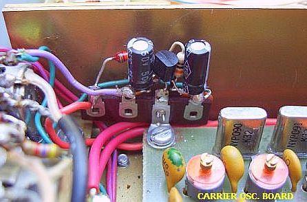
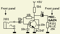
According to the manual, the impedance of microphone input (J101) is 25 kΩ. That was in the last century well suited for an average 50 kΩ microphone, but today is 200-600 Ω a more normal value. Unfortunately, the level is too low for this transceiver and therefore I used an earlier design for a Heil 4 & 5 microphone as amplifier.
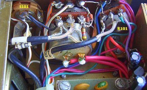
The components had to be mounted in the transceiver on the CARRIER OSC. BOARD because without damage of the set, on the front plate was no room for J101 («fig) to be replaced by a 4 pin microphone system. The extra pin was needed to provide a positive voltage for the preamplifier.
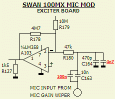
Hams reported the modulation sounded pinched with or without preamplifier. The audio on the Exciter BOARD was modified by respective a 100 nF capacitor in parallel with C163 (10 nF) and 4.7 nF in parallel with C164 (470 pF). Furthermore, the additional 4.7 nF capacitance is an extra RF decoupling of IC A103.
ALC
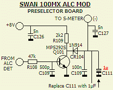
The release time of the ALC is slow, resulting in too much RF compression. That's too much at the wrong place and so capacitor C111 (10 µF) at the PRESELECTOR BOARD was replaced by a 1 µF type.
AGC
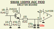
Personally I prefer a slower AGC which was obtained by the 220 µF capacitor in parallel with C132 (100μF) at the PRESELECTOR BOARD. Of course one may replace C132 by a 330 µF capacitor type.
RX OVERLOAD
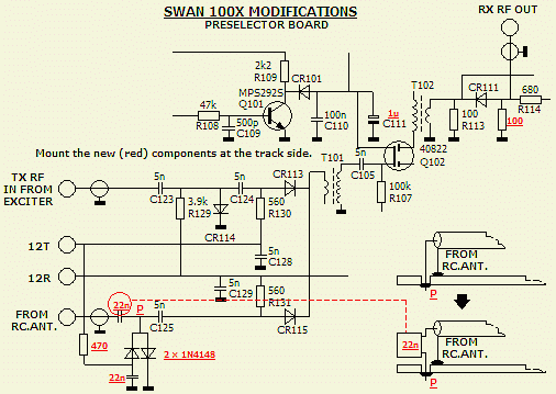
For a good overview, all preselector modifications were drawn in one schematic.
The receiver is overdriven with strong signals in the 40 m band. The additional 100 Ω resistor at the intersection of CR111 (BA244) and R114 (680 Ω) is a preliminary experiment. During reception, this component together with the conductive diode CR111 and resistor R113 (100 Ω) is an attenuator for the signal to the diode ringmixer. The gain also depends on Q102's drain load resistance, which is decreased by the extra 100 Ω resistor. Further the mixer-input load becomes approximately 50 Ω.
The overload is currently cured, but there is insufficient experience if it is indeed the correct remedy.
9000 kHz IF FILTER
|
Full size SHOWA filters. Model SF0922B: 8 pole 9000 kHz In en output impedance: 500 Ω BW: 2.30 kHz/-6 dB, 4.14 kHz/-60 dB |
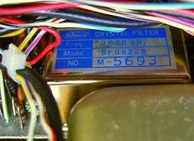
The original SHOWA IF crystal filter model SF0927A is 9001.65 kHz, BW 2.7 kHz. The plan was to replace with a KVG XF-9B, but I had a SHOWA («fig) SF0922B model in stock. It appeared that the assembly and pin connections were exactly the same as the original model, so it is like drop-in types, only the height was less. Because my experience with this filter in an FT7 was good, I decide to mount the narrow filter into this SWAN 100MX.
Via the Internet is such a filter still available and years ago I bought the same way in the USA. Eventually try the G-QRP club as a source.
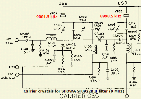
Although it probably is possible to pull down the original crystals 9000.0 kHz and 9003.3 kHz with additional capacitances in parallel with (fig ») C105 and C111, I replaced with 8998.5 kHz and 9001.5 kHz from a YAESU FT200.
In the LSB mode adjust C109 for 8998.5 kHz, in the USB mode adjust C104 for 9001.5 kHz and in the CW mode adjust C106 for 9000.7 kHz.
Test with a two-tone generator and the balance setting of T101 (carrier osc. board) proved it was better to set the LSB and frequencies at respective 8998.55 and 9001.55 kHz.
IF FILTER LOAD
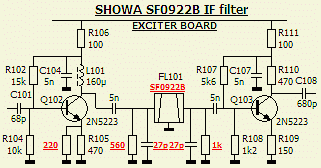
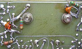
Initially the filter was installed without any modification to the circuit. Because it turned out to be a minor effort to load the filter with the correct impedance, I calculated («fig) the value of the additional components as close as 500 Ω. The resistors causes a drop of the gain and that was increased with a 220 Ω resistor in parallel to R105 (470 Ω). One can solder the new components at the trackside without damaging of the PCB.
![]()